Reversing old ECUs (P30 analysis p.2)
Now that we dumped the firmware, let’s see what that unknown tune is all about…
By the way
After the first part was published on Hackaday, I read a lot of comments saying that there was no point in doing what I was doing here, that I should just use an aftermarket ECU (??), that there were tools readily available to modify it, etc.
I KNOW that, but the purpose of this is for me to have something to reverse engineer to understand how it works, which is what those people that created the tools did years ago. I don’t actually care about modifying the ECU, Tuner-san and I already have good firmwares ready to run, but we are curious people who like to tinker and understand how things were done. I’m not filling a lack of tool here, but just trying to walk the steps of the first people who encountered a Honda ECU and tried to play around with it, out of CURIOSITY. All this information could be useful in a project where tools and documentation are not a thing.
If you can’t understand curiosity and learning for fun, just stop reading.
Back to our ECUs!
The firmwares
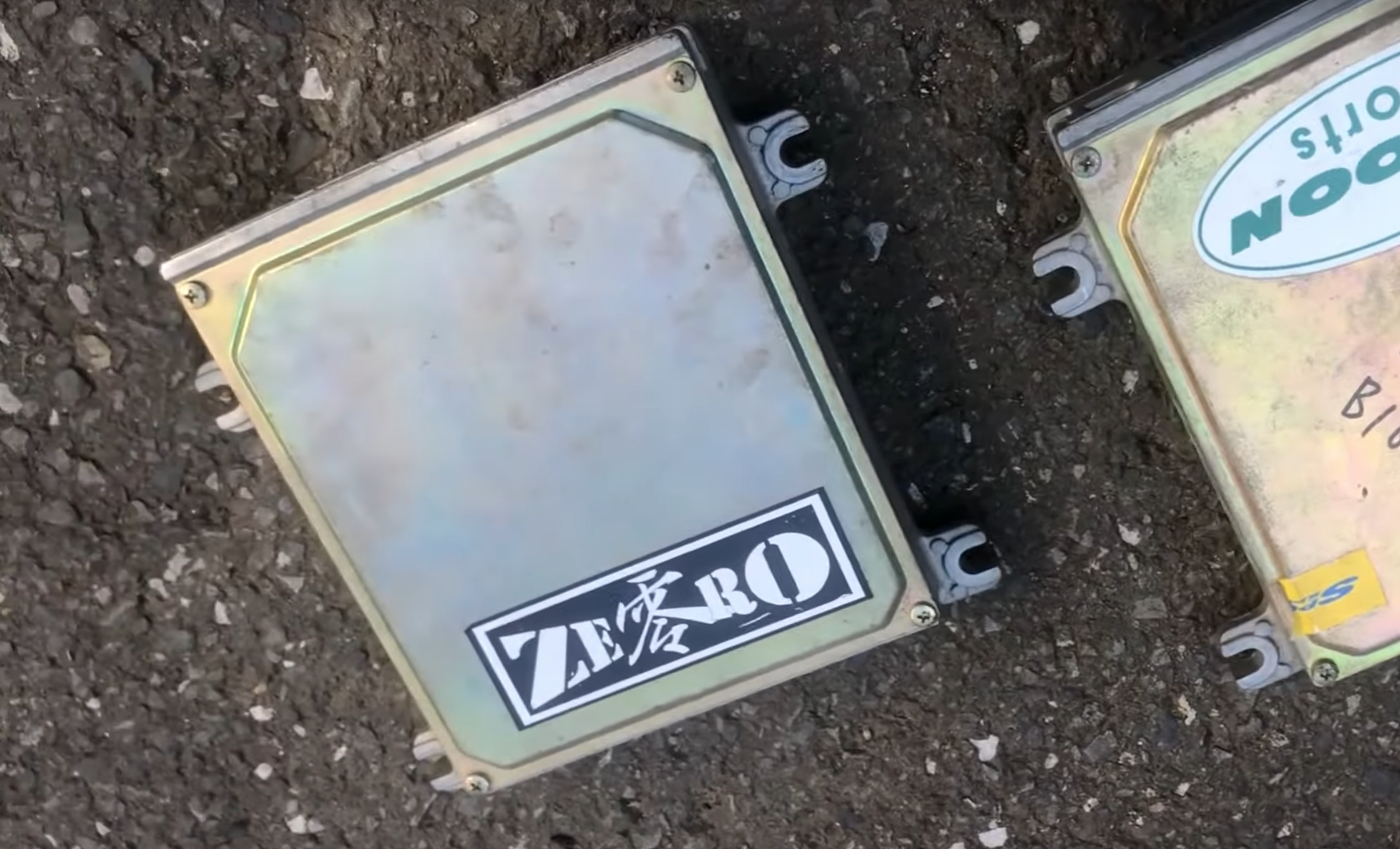
In this study I will look at three different firmwares: the stock one, the Spoon Sports one, and mine (the unknown one extracted from my car’s ECU, that we’ll call ZERO since this is what the big sticker on it says). Thanks to this, and with more diffing than reversing, I should be able to understand what my car’s tune is about, and what’s different from stock/Spoon. Then, if possible, I will try to modify and reupload the custom firmware on a different EPROM.
For copyright reasons, the dumped firmware will not be released, only extracts will be displayed.
There were a lot of revisions of this ECU, depending on country, year, engine, etc.
The part number on my ECU says P30-010, which is the JDM kouki (later) version of
the EG6. Oddly enough, after quickly checking against the Spoon P30-010 and
Spoon P30-000 (zenki - earlier) dumps, it seems that the code running
on the ECU is actually from a P30-000 version. The circuitry being similar
between both zenki and kouki, they probably just flashed their own 000 firmware
onto a 010 ECU. The firmware being 000, this is the version will be focusing on from
now on.
The stock firmware was downloaded from PGMFI (ECU ID 203). To verify it was legit, I checked a few addresses that contain known data (rev limiter and VTEC point for example, which are what people tend to modify first) and confirmed that they contained the stock value. The checksum was also equal to 0 (more info on that later).
I started by using binwalk -Wi to diff the Spoon firmware with the stock one,
and find what had been modified and thus where to look. We can see that the
speed limit is changed from 185kph (0xb9) to 255kph (0xff) at address 0x1831,
as well as rev limits on lines 0x637x and 0x638x, or VTEC [de]activation points
on bytes 0x643[6-9]. I don’t exactly know what operation is used to convert
those bytes to RPM. I wanted to solve it through a system of equations, but different
sources seemed to indicate that the value is not very accurate, so I just
ignored it (see Additional notes down there).
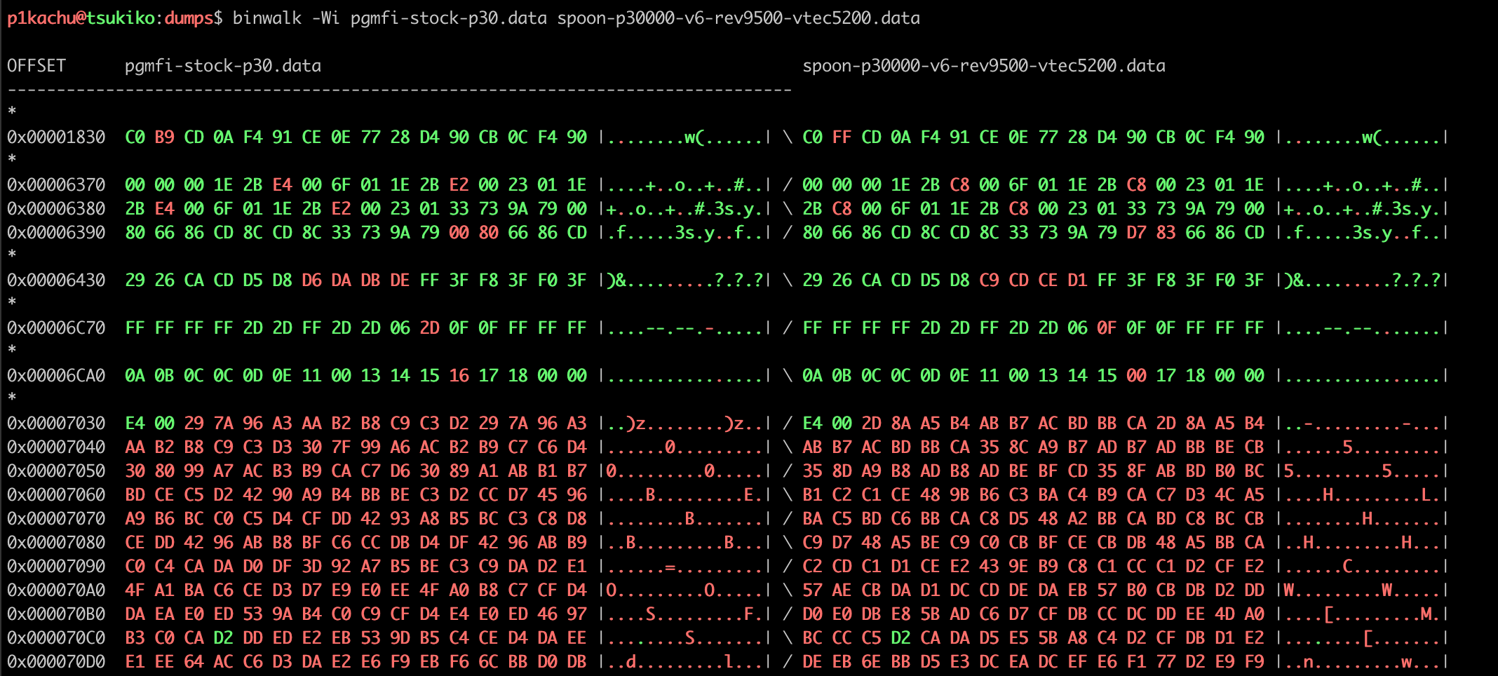
The biggest red blob is the Air/Fuel (A/F) ratio base map (see Additional notes). Spoon rewrote this map to give the engine a more aggressive tuning. The Ignition map (see Additional notes) was left untouched. I won’t explain here what those are about as I don’t want to get into engine tuning too much. I will try to focus on the ECU and computer science part mostly.
The last two lines are interesting. They show that some FF bytes in the stock
ECUs were replaced. If you look more closely with binwalk -W, you realize
that those bytes are not code at all, but just padding to fill the 32K of the
ROM, so why modify bytes there?

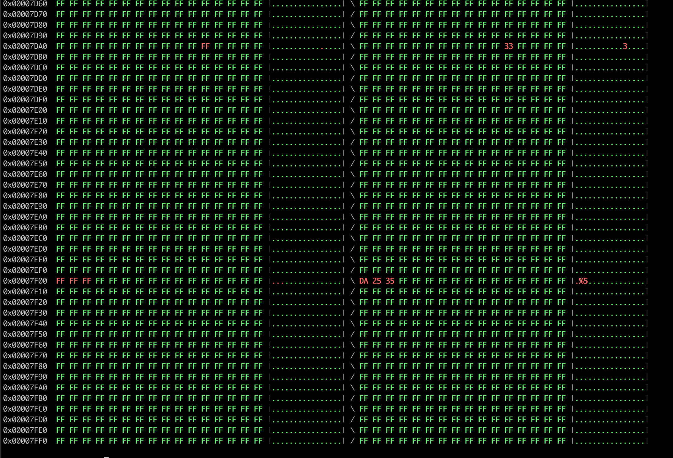
Tuner-san told me that back in the days, Honda already introduced a checksum in their ECUs to verify the integrity of the firmware. If the checksum wasn’t correct, the check engine lamp (CEL) would come up. He also told me that Spoon were the first ones to figure out the checksum and offer tuned ECUs that would not trigger the CEL, and this is one of the reasons their ECUs sold well despite being more expensive than competitors’. Those bytes at the end are how Spoon managed to fix the checksum issue, as it is just the 8bit addition (no carry, nothing, just roll the byte) of all the bytes on the firmware. If the sum is 0, then the firmware is “legit”, so Spoon would just increment a few bytes when needed until the checksum rolled back to 0x00.
Only one byte is required for that, so I suppose they either used more bytes as “signature” to determine which version of the firmware was written to the ECU, or to not have to re-erase the whole chip in between modifications when it was not necessary (you can easily program a 0xFF to any other value, but you can only turn 1s into 0s without having to erase so it’s easier to start from a fresh 0xFF byte). Since only the sum of all the bytes needs to be 0, you can write whatever you want in those 0xFF without altering the ECU’s functionalities.
- Modify the ECU
- Compute the checksum by adding all the bytes together -> XX
- if XX != 0: change one byte at the end of the firmware to (256 - XX)
HOWEVER. One interesting point about my ECU is that, while the checksum isn’t valid, it didn’t trigger the CEL on my car at all (the lamp still works when needed, but just not as a result of the invalid checksum). Could they have also removed the checksum check from the code? Could they have inverted the check so that only a valid checksum triggers the check lamp? Let’s try to find out.
Analysis of the ZERO ECU
Thanks to what we learned with the Spoon ECU, we should be able to see what has been modified in my ECU compared to the stock one. Let’s apply the same method to get a first overview, and see what’s different:
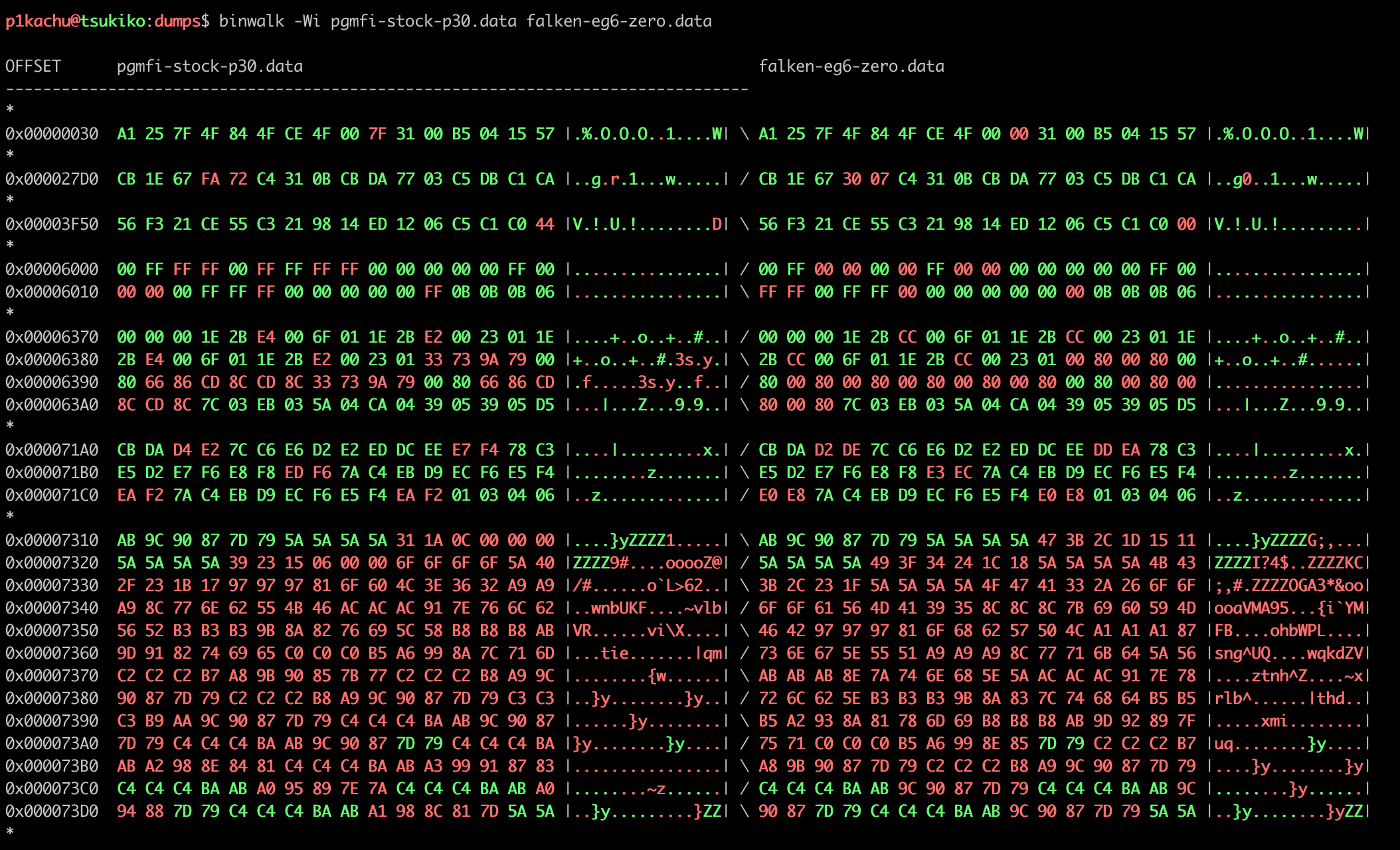
Since I don’t know where this ECU came from, there is no documentation readily available about most addresses. First weird thing I noticed is that the speed limiter’s value doesn’t seem to have been changed (one byte @ 0x1831), even though I know that the ECU allows me to reach speeds like 200kph easily. The rev limiter is quite high (the smaller the value, the higher the rev limit is: stock is 0xe4, Spoon is 0xd6, ZERO is 0xcc) which might be a bit dangerous. The A/F table’s axis were modified at addresses 0x6388 (12 bytes) and 0x6397 (12 bytes). The addresses 0x71A0 to 0x71C0 seem to contain part of the A/F tables, and the big blob at 0x7310 represents the Ignition table.
And that’s it. Not much was modified in this firmware (the VTEC points are still stock, surprisingly). I will ask Tuner-san what he thinks about the tuning itself (the Ignition and A/F table modifications), but we do want to know exactly why the invalid checksum doesn’t trigger the CEL and why the speed limiter isn’t activating when it should. I also noticed that a few switches had been toggled between addresses 0x6002 and 0x601B. By digging a bit more, I realized that the whole ECU seemed to be in debug/tuning mode (addresses 0x6005 and 0x6011). This could explain why the CEL was not on even though the checksum was invalid, but I will need to confirm this. So far, here are the differences between stock, Spoon, and ZERO.
P30-000 | Spoon | ZERO | Memo
-------------------------------------------------------
0039:7F | | 00 | ?
-------------------------------------------------------
1831:B9 | FF | | Speed Limiter
-------------------------------------------------------
27D3:FA | | 30 | ?
27D4:72 | | 07 | ?
-------------------------------------------------------
3F5F:44 | | 00 | ?
-------------------------------------------------------
6002:FF | | 00 | Knock Sensor (0xFF:ON/0x00:OFF)
6003:FF | | 00 | Oxygen heater Sensor (0xFF:ON/0x00:OFF)
6005:FF | | 00 | Oxygen Sensor (0xFF:ON/0x00:OFF)
6007:FF | | 00 | ?
6008:FF | | 00 | ?
6010:00 | | FF | Vtec VSS check (0x00:ON/0xFF:OFF)
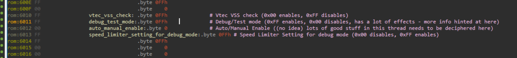
6011:00 | | FF | Debug/Test mode (0xFF:ON/0x00:OFF)
6015:FF | | 00 | ?
601B:FF | | 00 | ?
-------------------------------------------------------
6375:E4 | D6 | CC | Rev Limiter (Low cam set/reset + High cam same)
637B:E2 | D6 | CC | Stock: 8200 RPM
6381:E4 | D6 | CC | Spoon: 9100 RPM
6387:E2 | D6 | CC | ZERO : 9200 RPM
-------------------------------------------------------
638B:2x6 | | Modified | Base A/F Low
6397:2x6 | | Modified | Base A/F High
-------------------------------------------------------
6436:D6 | C9 | | VTEC Point (#3 and #4, reset then set)
6437:DA | CD | | Stock: 5500 RPM
6438:DB | DE | | Spoon: 5200 RPM
6439:DE | D1 | | ZERO : 5500 RPM
-------------------------------------------------------
6C7A:2D | 0F | | ?
6CAB:16 | 00 | | ?
-------------------------------------------------------
7032:10x21 | Modified | | A/F Low
7104:10x21 | Modified | Modified | A/F High
71D6:10x12 | | | A/F Correction
-------------------------------------------------------
724E:10x20 | | | Ignition Low
7316:10x20 | | Modified | Ignition High
73DE:10x11 | | | Ignition Correction
-------------------------------------------------------
Modified in the ZERO ECU:
- Base A/F, A/F (high) and Ignition (high) maps (this much makes sense)
- Rev limiter at ~9200 RPM (a bit high imo)
- Knock sensor disabled (some hardware doesn't have a knock board, is it the reason?)
- Oxygen heater sensor disabled (same, some ECUs do not have heater control)
- Oxygen sensor disabled (necessary to tune the maps)
- Debug mode enabled (necessary to tune the maps)
- VTEC VSS check disabled (no need to be at a certain speed for VTEC to engage)
All of this still doesn’t explain why the speed limiter is not triggered even though the value is stock and why the CEL is off when the checksum is invalid. So we’ll have to load the firmware in IDA.
Reverse engineering the firmware
Thankfully, I had already started working on this months ago when I was playing around with my DC2’s ECU, and wrote an experimental IDA loader to start reversing the firmware. It’s not the best but at least it allowed me to run some IDAPython scripts around the firmware to find Xrefs from code to the data I was interested in, and to try to understand what parts of the code had been altered.
Compared to recent ECUs or software in general, this kind of firmware always shows some challenge. First thing I saw was that a lot of routines seemed to be written like MACROs, with sometimes two or more functions sharing code: for example, an Interrupt handler would at some point jump into another handler because they share the same kind of clean-up/epilogue. IDA doesn’t really let you handle that correctly (as far as I know), so I could not define functions the way I wanted. Another thing, related to the architecture itself this time is that the same opcode can have different meanings at runtime depending on the status flag called DD. You can try to track DD during disassembly (I do) but since IDA is multithreaded in its analysis, you frequently stumble upon some weird results with instructions changing depending on where you start reading/analysing.
All in all, the disassembly was far from being reliable, but good enough to let me look around and poke at things.
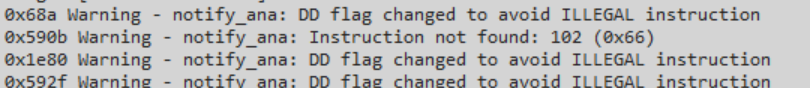
Why is the CEL not turning ON even though the checksum is invalid?
This is the question I wanted answered and it actually took less than 5 minutes to find the reason. The routine responsible for the checksum begins around 0x282a in the P30 firmware, and the “Checksum OK” branch is at 0x2867. By looking at the Xrefs to this address, I see that there are three ways to actually take this branch. I don’t really understand the first one to be honest, as the whole checksum loop code doesn’t make much sense to me and it might be due to erroneous disassembly.
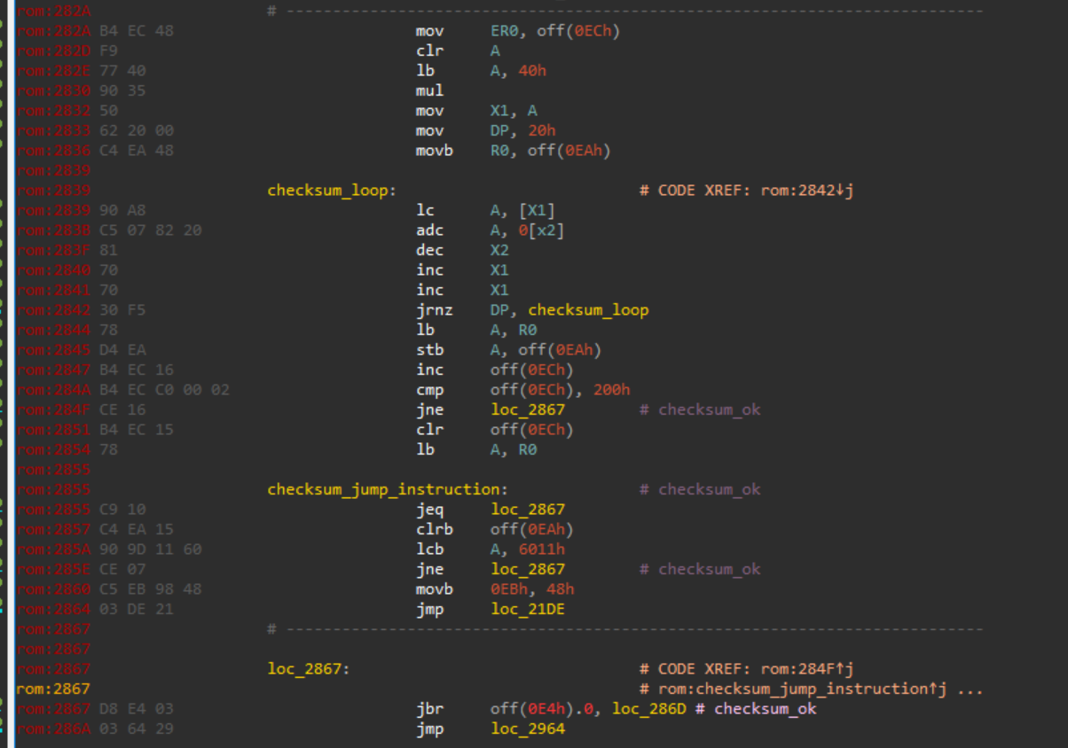
However, the second conditionnal jump there seems to be the way to avoid the checksum (replacing the conditonnal jump by a solid jump is how PGMFI recommends bypassing the whole routine). On my ECU, the code is still stock and the conditionnal jump is still there, so this is not why the CEL is not triggered.
I then looked at the third condition (address 0x285e), which takes the branch if the byte at address 0x6011 is non-null. What is this byte? The debug mode. By setting the debug mode byte to a non-null value (in our case, 0xff), we effectively bypass the checksum, as expected.

For the sake of completeness, if I do manage to reflash the ECU later, I will try putting it back into non-debug mode without changing anything else to see if I was right. But for now, I think it’s safe to assume this is the correct explanation.
Why is the speed limiter not triggering even though the value hasn’t been modified?
First of all, according to PGMFI, there are a few switches and addresses related to the speed limiter. The first obvious one, which raised this very question, is the limiter value itself found at address 0x1831. In the stock ECU it’s 0xb9 (185 kph) and was modified in the Spoon ECU to be 0xFF (255kph), as this speed is unreachable on a stock engine/transmission anyway.
However, on the Zero ECU, it still contains the stock 0xb9 value, which should prevent the car from going faster than 185km/h… but it doesn’t. Why is that?
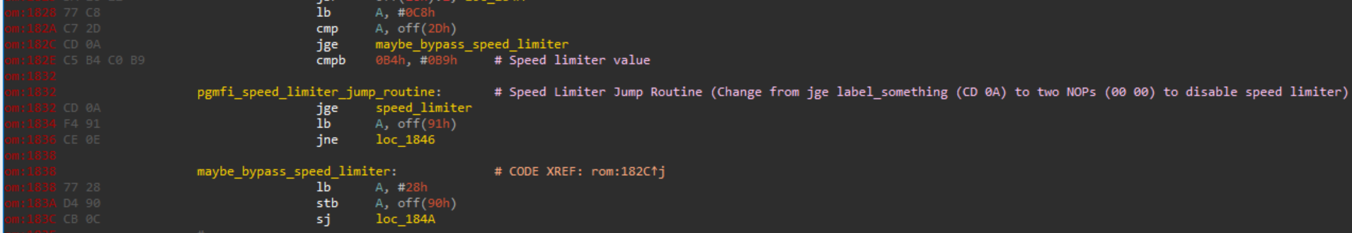
First possibility is, the code itself was modified (NOP a jump or NOP the whole check), but after looking around the code, there doesn’t seem to be anything of the sort in this area. The code is still there, and the same as factory ECUs.
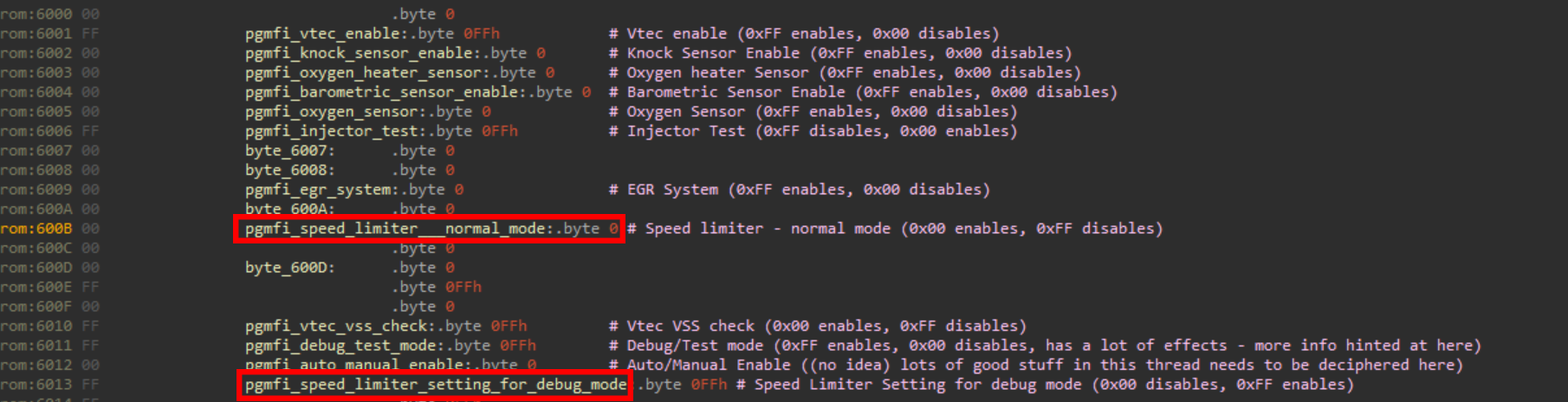
Second possibility is, PGMFI talks about two switches used to enable/disable the speed limiter in normal (0x600B) and debug mode (0x6013).
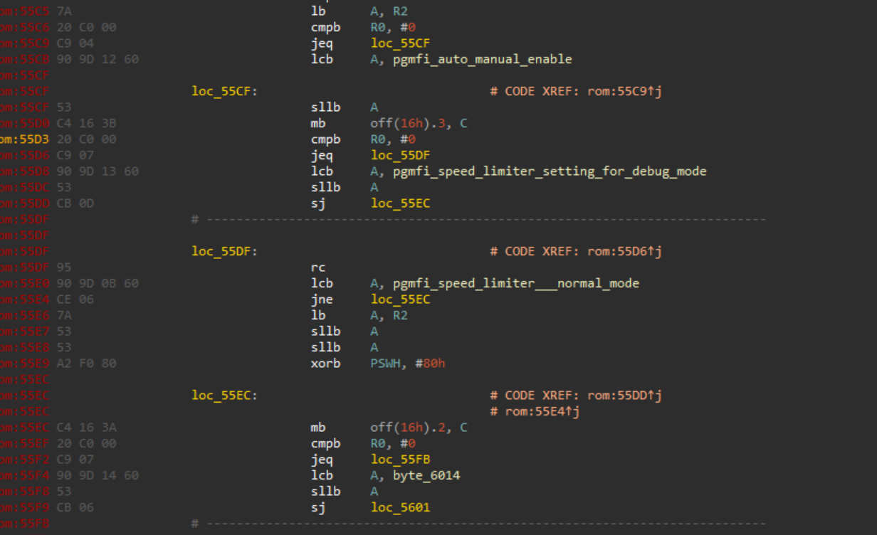
They are used in a region of code that checks all those switches, but they both seem to be turned in a way that would not disengage the speed limiter (normal mode one is turned ON, debug mode one seems to be turned ON too, but this depends on what the PGMFI guys meant by “Speed Limiter Setting for debug mode”).
Since I didn’t find any way to compare my IDA disassembly output to anything else, I wasn’t sure that I was reversing properly disassembled code. Either way, digging a bit around the code didn’t raise anything else but the debug mode assumption. I will also try confirming this assumption when reflashing the firmware.
If things work the way they are expected to, reflashing should be the next (and final I guess) part of this article. Feel free to ask any detail/question on Twitter. Most scripts and code will be posted on this Github repo when the article is complete.
Thanks for reading~
Additional notes (that just didn’t fit in the main explanation)
-
RPM values don’t seem to follow a very clear rule (I would need to find the routines to understand how the values are used). Some sources seem to say that dividing 1875000 by the value would give the RPM, but it doesn’t work for the VTEC points and gives slightly off values for the redline. So the values written in the “Memo” column in the Reverse engineering section should be taken with care.
-
Air/Fuel (A/F) tables are used by the ECU to determine which ratio of fuel vs. air to inject in the engine depending on engine load and engine speed. Advance/Ignition table are used to determine when to fire the sparkplug in each cylinder. Modifying those tables is what constitutes the biggest part in tuning an engine.