A tour of automotive systems from 20 years ago
276hp at 1953 bauds, communicating with the elderly
This project was presented at BlackHat Europe 2019. Video available through BHEU’s VOD services.
I moved to Japan mid-2017 and bought an old [90’s car]. While old, this car became my daily driver, as well as my track and tōge ride. It definitely is a nice car to play with. At that time, I was still working on my custom IVI and decided to add the support for this car. The idea for me was to be able to recover basic engine info in real time, and send them to the IVI. Of course, devices and softwares already existed, but I wanted to do it myself, as I knew I would learn (useful ?) stuff.
DISCLAIMER: This work has been done in order to learn about ECUs and to use the full power of the car on racetracks and closed roads only. While this can be applied to any car from this era and is a common practice amongst enthusiasts who don’t want to go aftermarket, I was asked to remove the car’s precise model information for legal reasons.

Step one: reconnaissance
The car features an OBD-II port under the steering wheel, but I knew that
chances of it supporting CAN were very slim. Digging through google and twitter
raised an acronym: xSM, which stands for [THAT MANUFACTURER] Select Monitor.
To this day, it seems that [THAT MANUFACTURER’s] vehicles still support different versions of this protocol
(the latest one being xSM4), in addition to CAN. The one that my car supported
was either the first or second version.
To find out which version I was dealing with, I just had to check whether the OBD-II K-Line pin (pin 7) was connected or not. I could have used an oscilloscope, but removing the panel and checking directly was quicker:
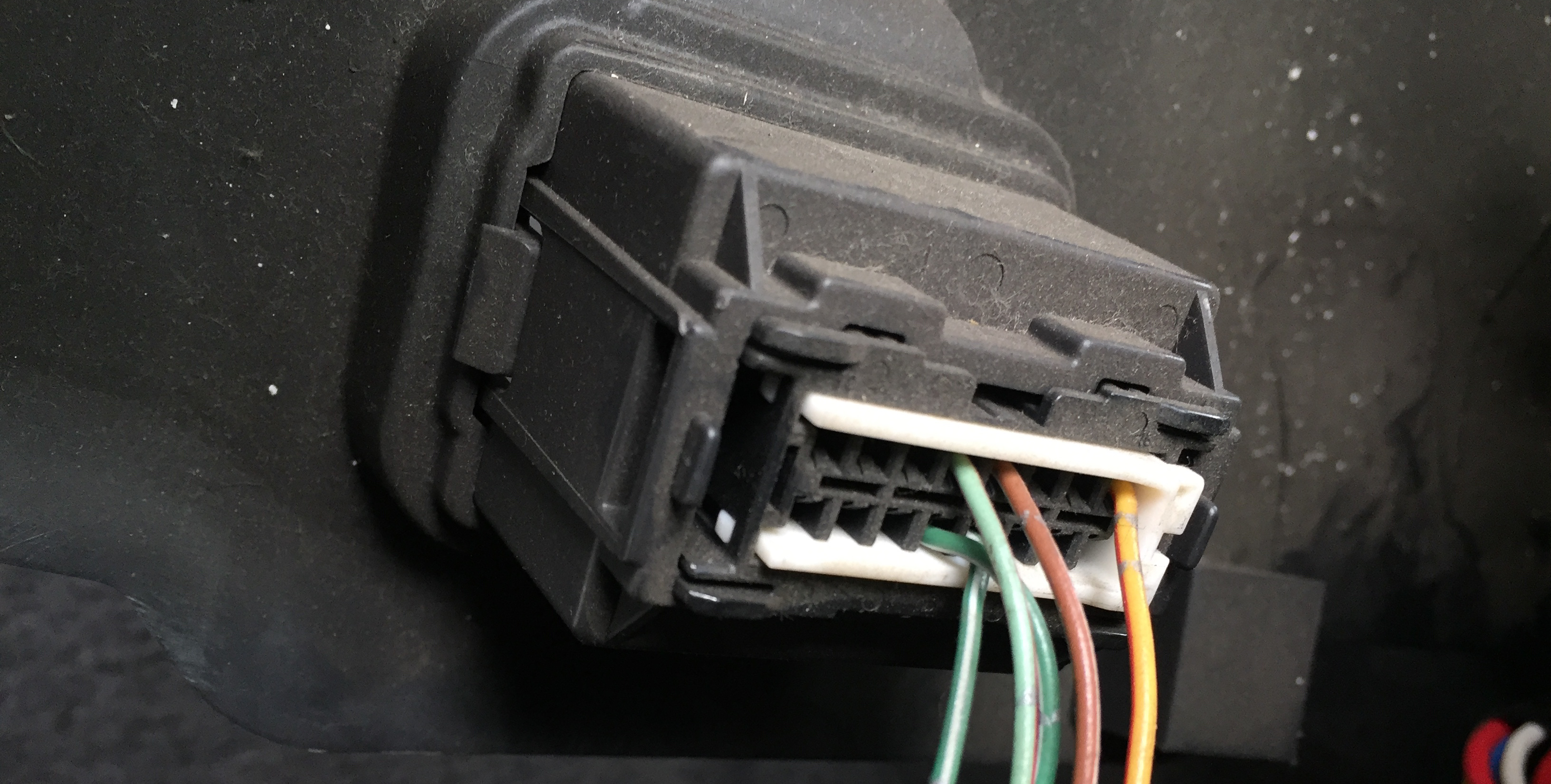
We can see that the K-Line pin is not connected. This means that this is not xSM2. However, we can see that the power pin is connected (orange), and that two Vendor Option pins are connected too (top two wires, which are usually used for constructor specific protocols). The two bottom lines are Signal ground and Chassis ground.
No K-Line, xSM1 it is. I thus began looking for information on how to interface with it. The xSM1 protocol is a simple serial protocol running at 1953 bauds at 5V TTL. TTL means Transistor-Transistor Logic, meaning it relies on circuits built from bipolar transistors to achieve switching and maintain logic states (TTL gates define a below 0.5V as 0, and a voltage of 4–5V as 1).
Summary, it shouldn’t be too hard (if you don’t have a defective level shifter).
Step two: communication
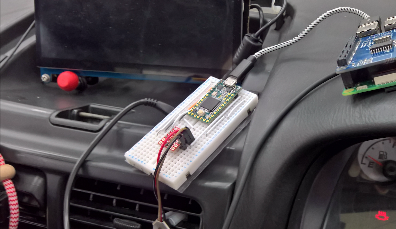
The protocol itself was pretty well documented on Alcyone, but I still needed the hardware to handle such communication. I took a simple Teensy 3.2 and a custom made OBD-II connector, and started from there. Since the Teensy’s serial pins are only dealing with 3.3V signals, I added a level shifter (also called Logic Level Converter) to convert the Teensy’s 3.3v to the car’s 5v. I could have directly soldered the level shifter’s pins to the wires behind the panel, but I wanted to avoid any destructive modification if possible (spoiler: not anymore). Hardware devices are still sold for this protocol (like BluexSM for example), but I had more liberty querying values by writing my own software, instead of having to rely on an interface. Following is a picture of the early setup (the PiCAN2 shield is there because I still used it for other projects, but is useless here).
xSM1’s protocol is well described here, but as an overview, here are the commands I used for this project:
00 46  48  49 -> Get ROM ID
78 msb lsb 00 -> Read data from ECU address
12 00  00  00 -> Stop
Querying data was then possible using the information recovered from obscure [THAT MANUFACTURER] forums. I finally found which address was related to which data, and how to interpret them (almost, I still have doubts about how to read the MAP value).
// Used addresses
#define BATTERY_VOLTAGE_ADDR      0x0007
#define SPEED_ADDR                0x0008
#define RPM_ADDR                  0x0009
#define COOLANT_ADDR              0x000A
#define AIRFLOW_SENSOR_ADDR       0x000C
#define THROTTLE_ADDR             0x000F
#define MANIFOLD_PRESSURE_ADDR    0x0020
#define BOOST_SOLENOID_ADDR       0x0022

// Not yet used ones
#define IGNITION_ADVANCE_ADDR     0x000B
#define ENGINE_LOAD_ADDR          0x000D
#define INJECTOR_PULSE_WIDTH_ADDR 0x0010
#define ISU_DUTY_VALVE_ADDR       0x0011
#define O2_AVERAGE_ADDR           0x0012
#define O2_MINIMUM_ADDR           0x0013
#define O2_MAXIMUM_ADDR           0x0014
#define KNOCK_CORRECTION_ADDR     0x0015
#define AF_CORRECTION_ADDR        0x001C
#define ATMOSPHERIC_PRESSURE_ADDR 0x001F
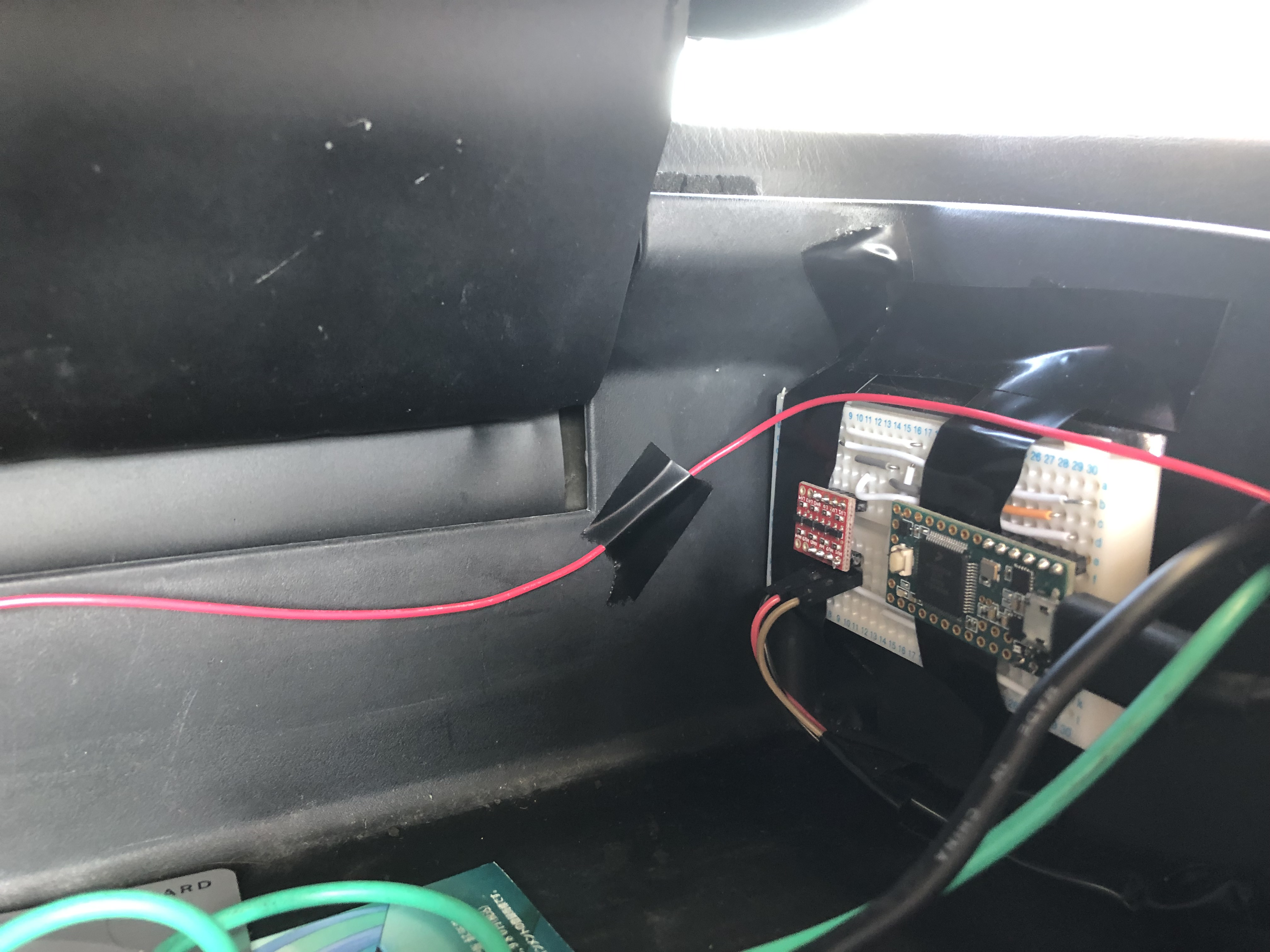
I neatly tucked the teensy circuit in one of the glove box, wired everything behind the IVI, and sent data over USB to the tinkerboard for reading and displaying.
Step three: Dumping and reverse engineering
In the end, I decided to dump the whole ECU (64kb long) by issuing read commands at every single address. It took around 9 hours to get the whole ECU, since I was reading each address at least twice (to be sure). The ECU sends one result each time it calls the communication routine, so changing the baud rate only wouldn’t really affect how many I could query per second. To avoid running out of battery, I plugged an external charger to the car’s battery.
This allowed me to get my hands on a 0x10000 bytes long binary blob. I still needed some information about the processor, so I decided to inspect the ECU itself which was hidden under the passenger floor mat.
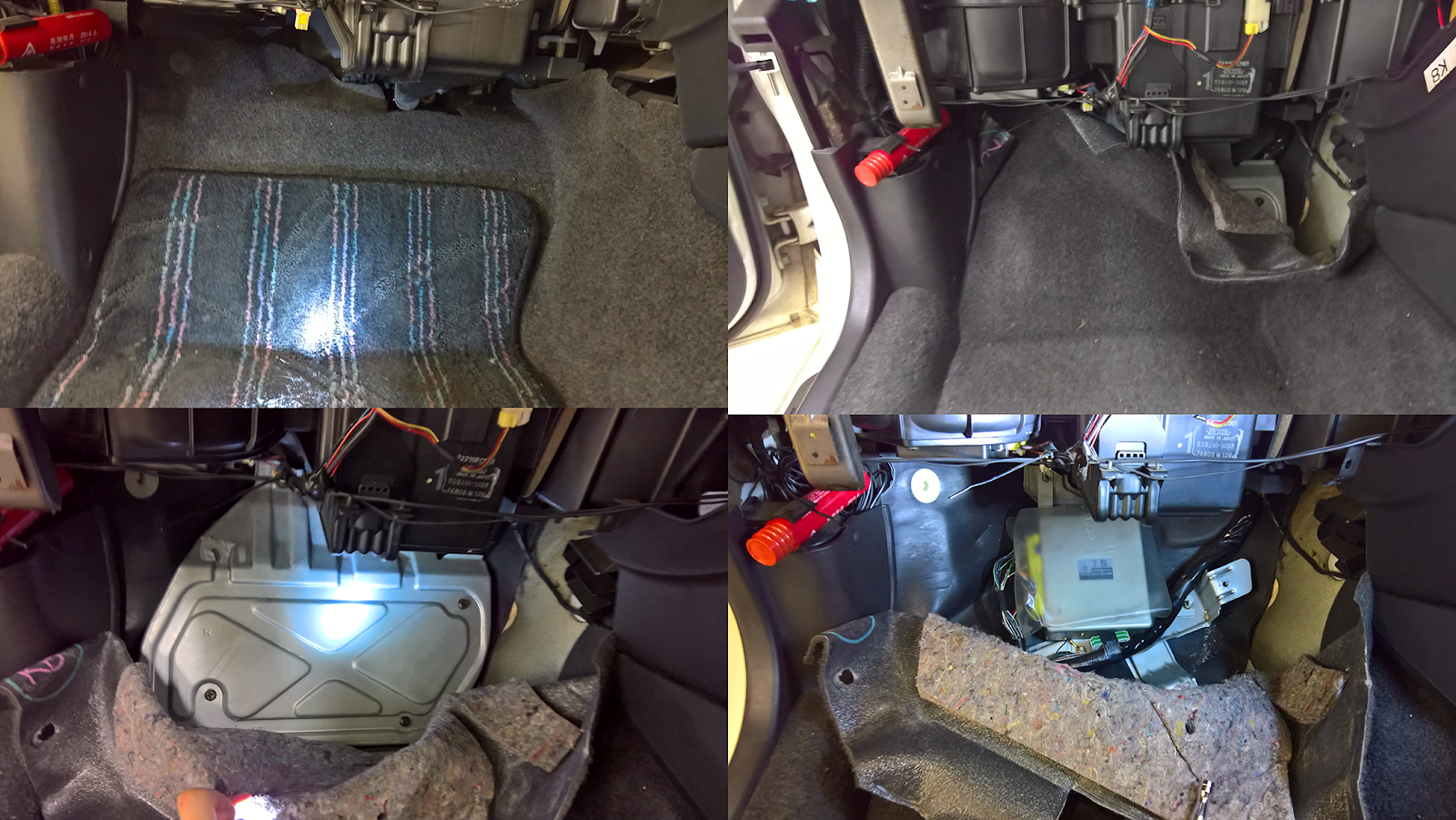
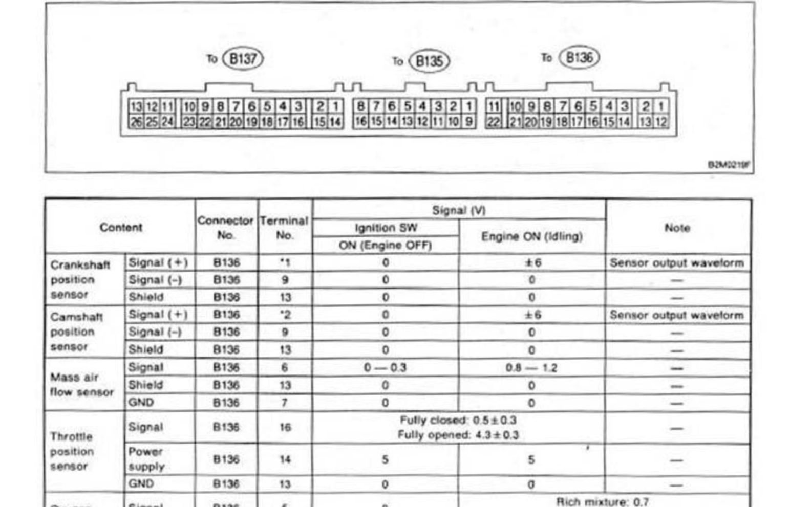
The ECU is a ~20cmx20cmx5cm metallic box with 3 connectors (identified as B135, B136 and B137) for a total of 64 pins. The whole ECU pinout is documented on multiple forums and ESL, which helped determining which pin was responsible for which sensor (useful for later).
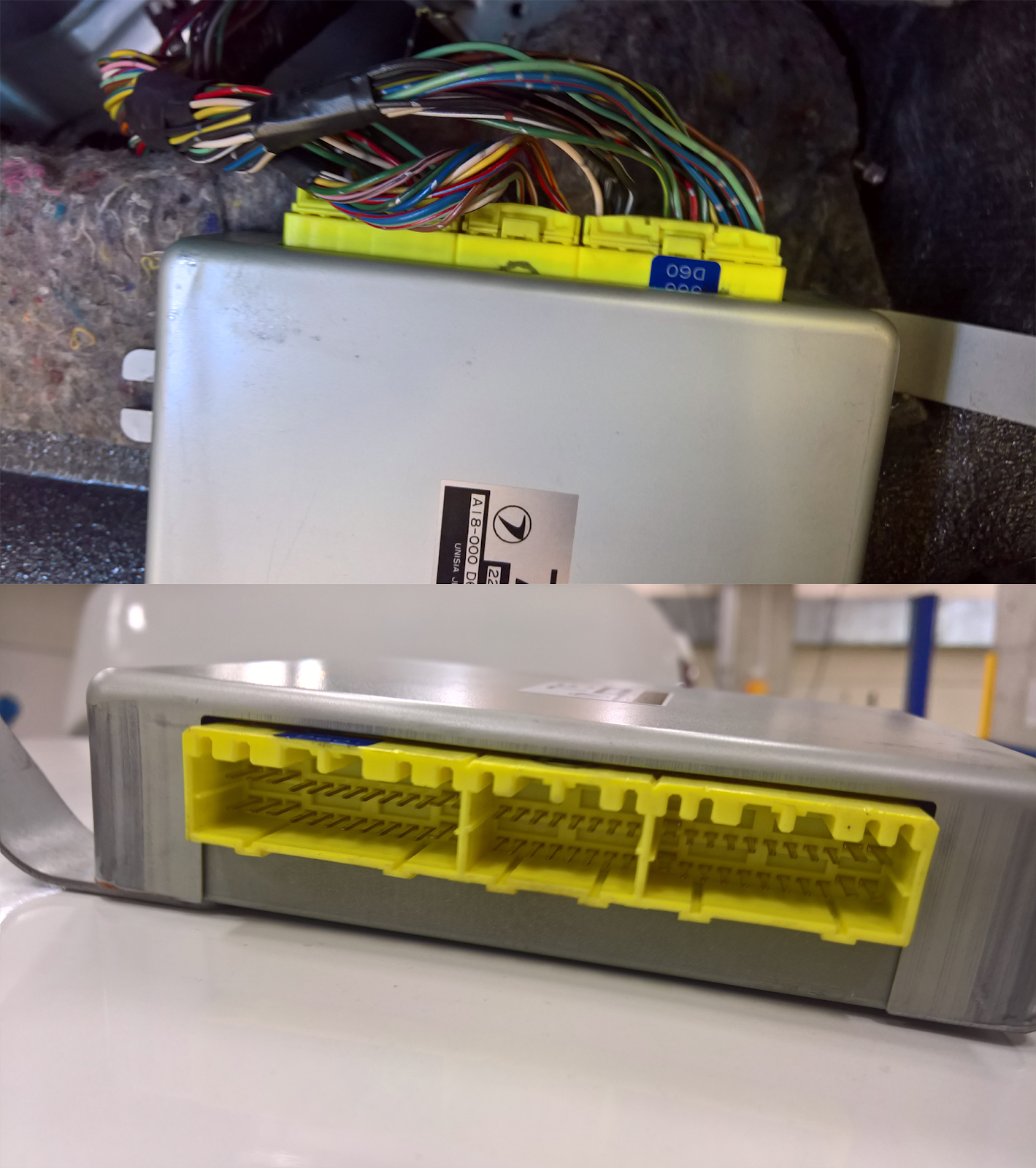
Opening it reveals a very well conserved board: the engine’s brain. Here is a short description of what can be found on the ECU:
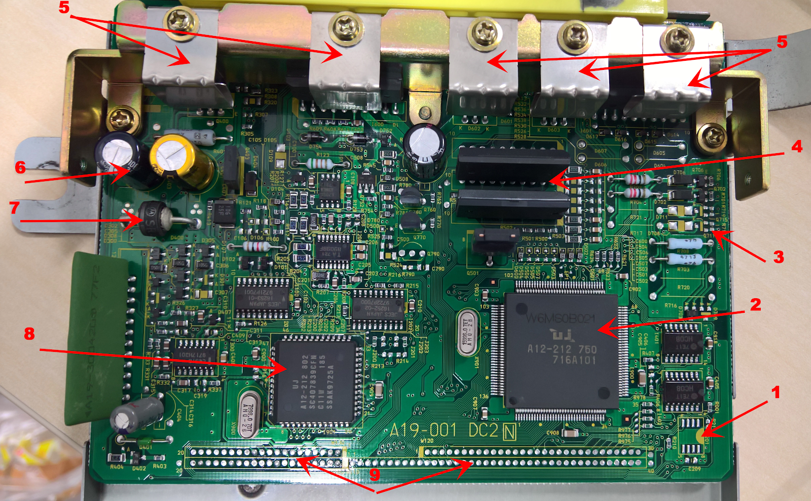
- 1: Slot for an immobiliser chip (Not present on Japanese ECUs like this one, more infos here)
- 2: Main CPU + embedded firmware. Custom JECS IC.
- 3: Ignition circuitry
- 4: Lower power transistors
- 5: Heat sink with heat clamps (High power transistors)
- 6: Power management circuitry
- 7: Diode to prevent destruction if the positive charge and negative charge are inverted
- 8: Secondary custom IC
- 9: Contact strip
The contact strip can be used to add a daughterboard to the ECU, which is for example what Enduring Solutions Limited do when they want to prepare [THAT MANUFACTURER’s] cars.
Some more research revealed that this IC was based on the Mitsubishi M37791 CPU (7700 family). One of the difficulties of disassembling m7700 code is that there is an “M flag” that changes the instruction decoding at runtime, but IDA still does a fine job. Poking around a bit revealed the location of fuel, ignition timing and ignition advance maps.
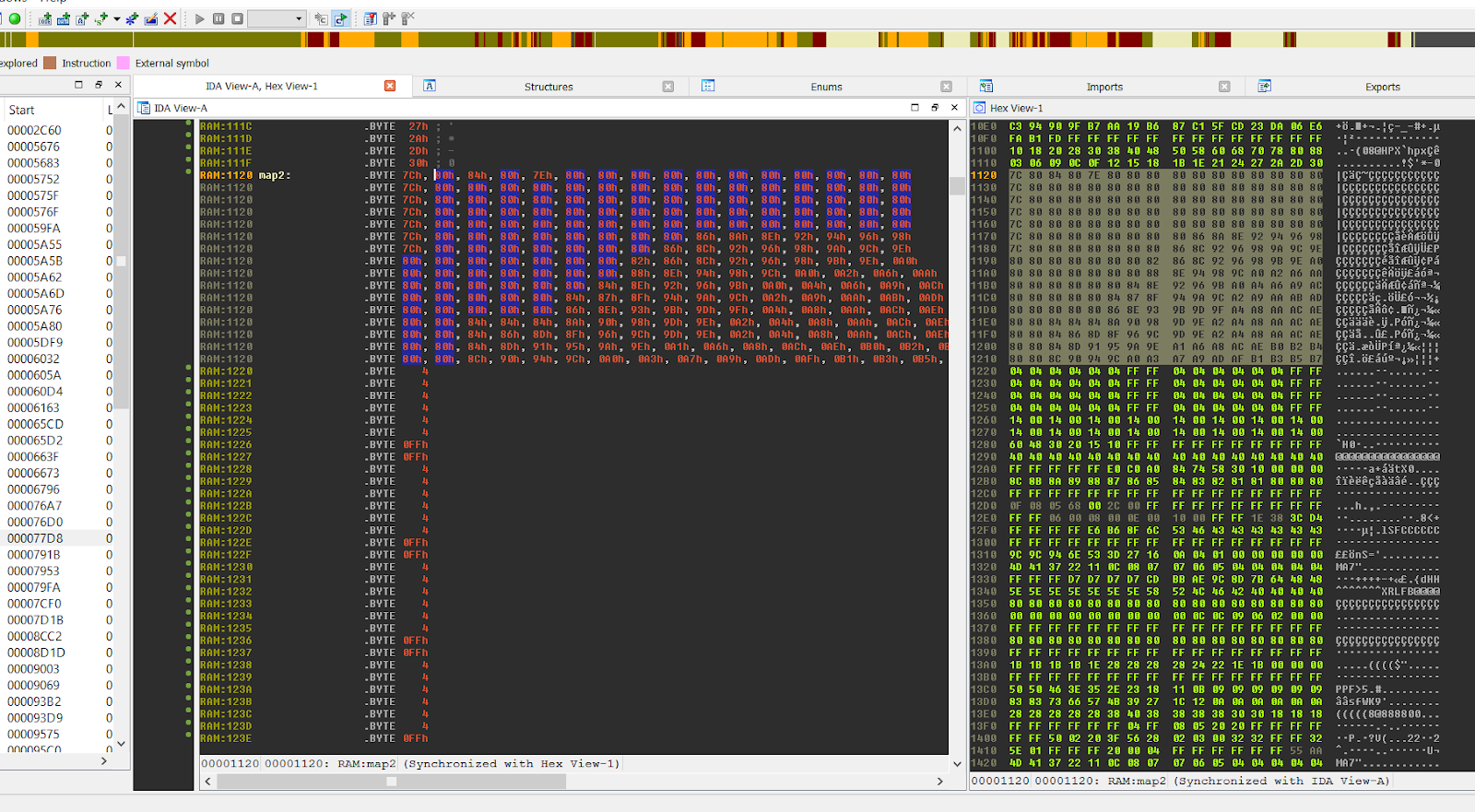
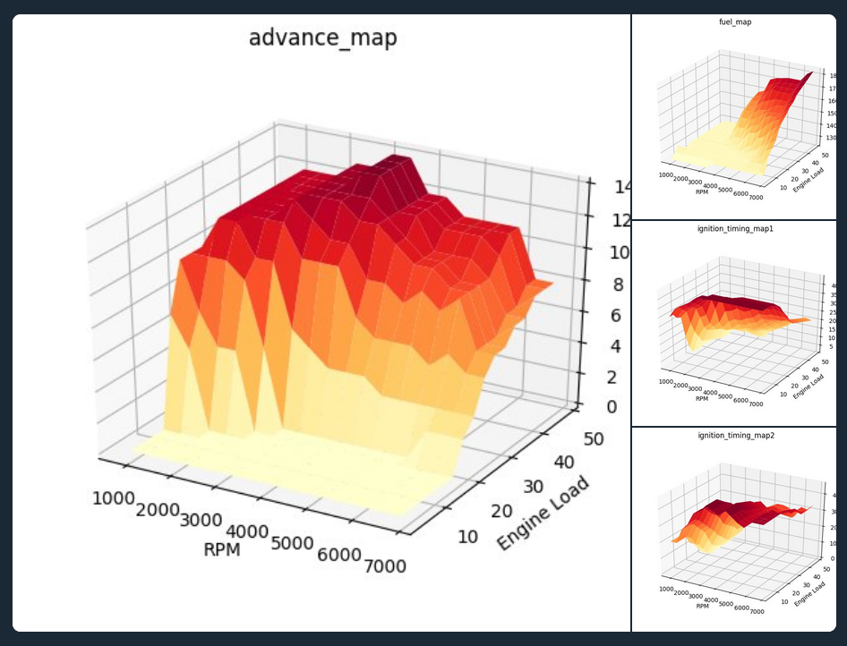
Following is a 3D representation of said maps using python and matplotlib (scripts available in the repo).
Step four: Bypassing the speed limiter
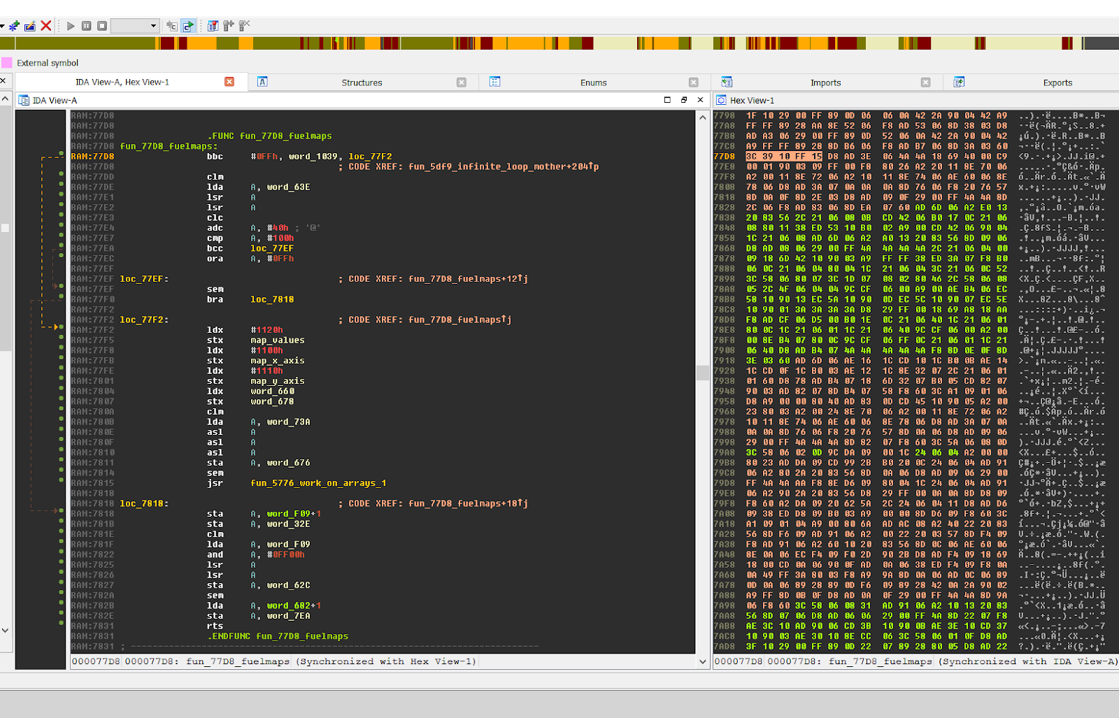
Another thing I realised when taking the car for testing on the track is the presence of a speed limiter. When reaching a certain speed (around 186 km/h), the ECU would just cut off fuel injection, which would make the engine stall suddenly for a short moment, before reactivating the injection when a fixed, lower speed was reached. After digging a bit in the code, I found the function responsible for that. While doing multiple things (the function is more than 0x300 bytes long), the interesting part can be seen in the following screenshot.
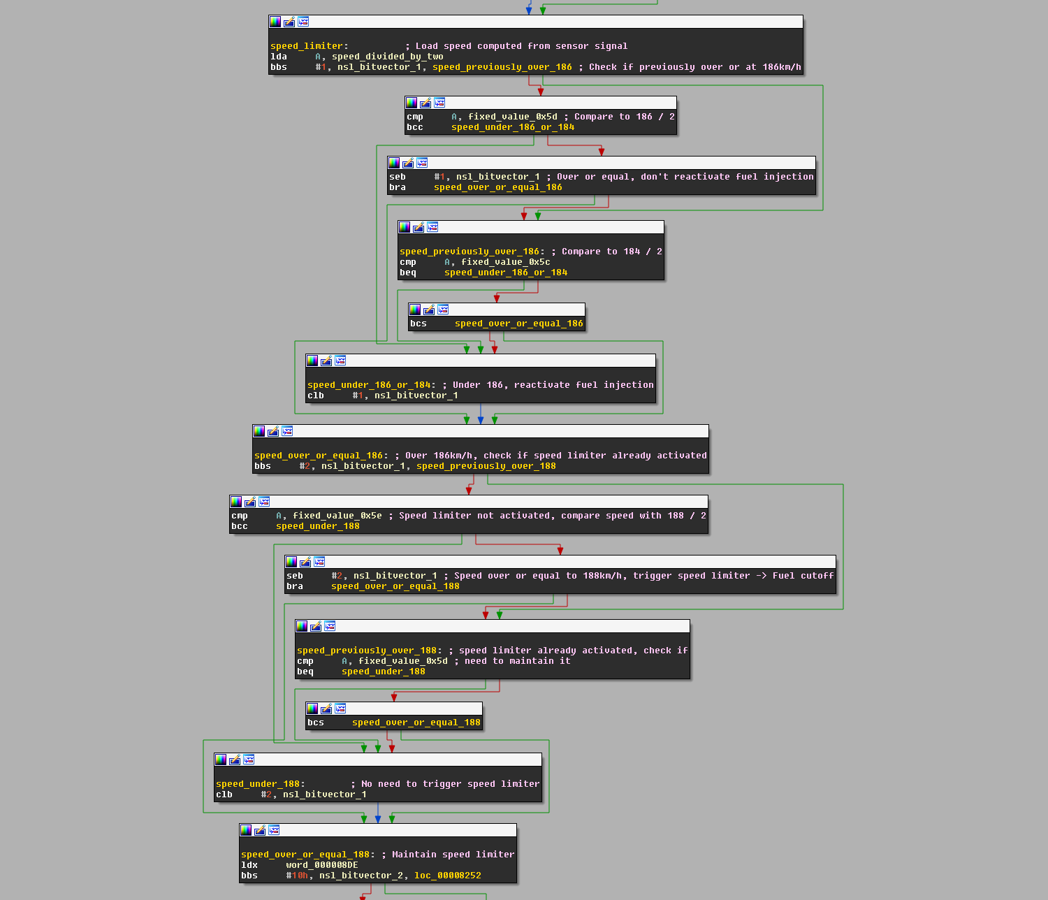
The exact speed at which the limiter kicks in is 188km/h. When this speed is reached, the speed limiter is activated and the fuel injection is cut (nsl_bitvector_1, bit 2). When the car’s speed decreases, checks are made to know when to reactivate the fuel injection. If the speed is 186, nothing happens, and the ECU waits for either 184km/h (reactivate fuel injection) or 188km/h (maintain fuel cut) to be reached to take a decision.
Three options were considered to bypass this speed limiter:
- Modify the ECU’s firmware (requires a daughterboard on top of the motherboard)
- Disconnect the vehicle speed sensor (or VSS)
- Fool the speed sensor signal
The first one presented a lot of difficulties (creating a daughterboard to reflash the firmware is not something I know how to do at the time of writing, to be honest). The second one had a major downside, which was that no speed information would be available to the engine and while it could run without, this can causes issues described below.
Interlude: Maps and speed sensor
While the engine could run without a speed sensor, some issues can arise depending on what this signal is used for. What I will explain here does not necessarily hold true for my car, but is more of a “this can be found in some, so let’s not take any risk”. You may want skip this part is you have no interest in engines and why this option is not recommended.
Engine ECUs (with the arrival of electronic fuel injection) use maps to
determine different variables that make the engine run. The quantity of fuel to
mix with air in the cylinders (fuel maps), the ignition advance and base timing
(advance maps/timing maps, when to fire the sparks plug in function of the
position of the piston), and such. These maps usually depend on the current
RPM and the engine load (how much “power” is requested by the driver from
the engine; this can either be the throttle pressure percentage for
NA engines, or the
MAF value for forced
induction ones). Examples of
such maps can be seen above. As the speed does not affect these maps, a VSS is
not mandatory.
However, disconnecting the speed sensor isn’t 100% without side effects, as
some cars have slight engine mapping tweaks depending on different speeds. For
example,
BNR32
ECUs seem to have 3 maps: the idle map (when the car is in neutral), the
transition map, and the full map (same as transition map, but with more timing
advance). The full map is activated by the VSS and has things like closed loop
O2 sensor feedback (correct the fuel injection depending on the combustion, by
checking the O2 level in the exhaust gases) as well as fuel cut on
deceleration. Power-wise, the worst that could happen is being stuck in the
transition map, which would not make as much power as the full one, but
engine-wise, the problem would be running lean (not enough fuel for the amount
of air), which could damage it. Another example, BNR32s also use the speed
sensor to trigger HICAS, Nissan’s rear wheel steering
system.
Anyway, back to our signal
Fooling the speed sensor signal was worth a shot as it was pretty easy to implement and could still allow speed information to be sent to the engine. I could at the same time test the second option just as a PoC, to verify that only the speed was used in the speed limiting process.
The VSS can have multiple forms, but judging by its signal, its
basic behavior can be described as a Hall Effect sensor, and represented as follow
(source):
The wire responsible for carrying the signal to the ECU is on the middle connector (B135, pin 3). This signal is an analog signal that switches between 0v and 5v following the speed of the car. The faster the gear turns, the higher the frequency. The number of “edges” is then recorded by the ECU in a specific time interval, and the speed is deduced from this. Cutting this wire, and adding a Teensy 3.2 in between (with another level-shifter, as the Teensy still only works with 3.3v) did the trick in successfully monitoring the signal. Having the teensy’s LED blink at each edge was the simplest way to get a direct visual representation of the speed.
From this I could receive and forward the signal. The next step would be to
modify it when a speed of 180km/h or more is reached only. This would prevent
strange behaviors of the engine from happening at lower speed (speed at which
the car is 99% of the time). I did some tests, and managed to have my IVI print
354km/h while being stationnary, which triggered the speed limiter, cut the
fuel injection, and stalled the engine. Meh, at least it works!
Determining the number of edges read in one kilometer was required, to properly convert a frequency to a speed, so I drove 100 meters and monitored the number of edges to get a rough value. The result seems to be around 200 edges/100m, so around 2 edges/m. Further testing showed that the value was not completely accurate, but fair enough for a PoC.
I was able to fool the ECU easily into thinking the car was going 140km/h while stationary just by sending a signal that edge’d once every 5 milliseconds approximately. The Teensy is able to keep track of the real speed at all time, and thus is able to send the real speed when it is less than 180, or just a delay(5) loop when it is over this speed, to avoid triggering the limiter.
Below is a simplified version of the code running on the Teensy:
while (speed >= 180) {
        if (previous_signal_value) {
                signal_value = 0;
        } else {
                signal_value = 1023;
        }
        analogWrite(VSS_TX, signal_value);
        delay(5); // Speed recorded is around 140km/h
        previous_signal_value = signal_value;
}
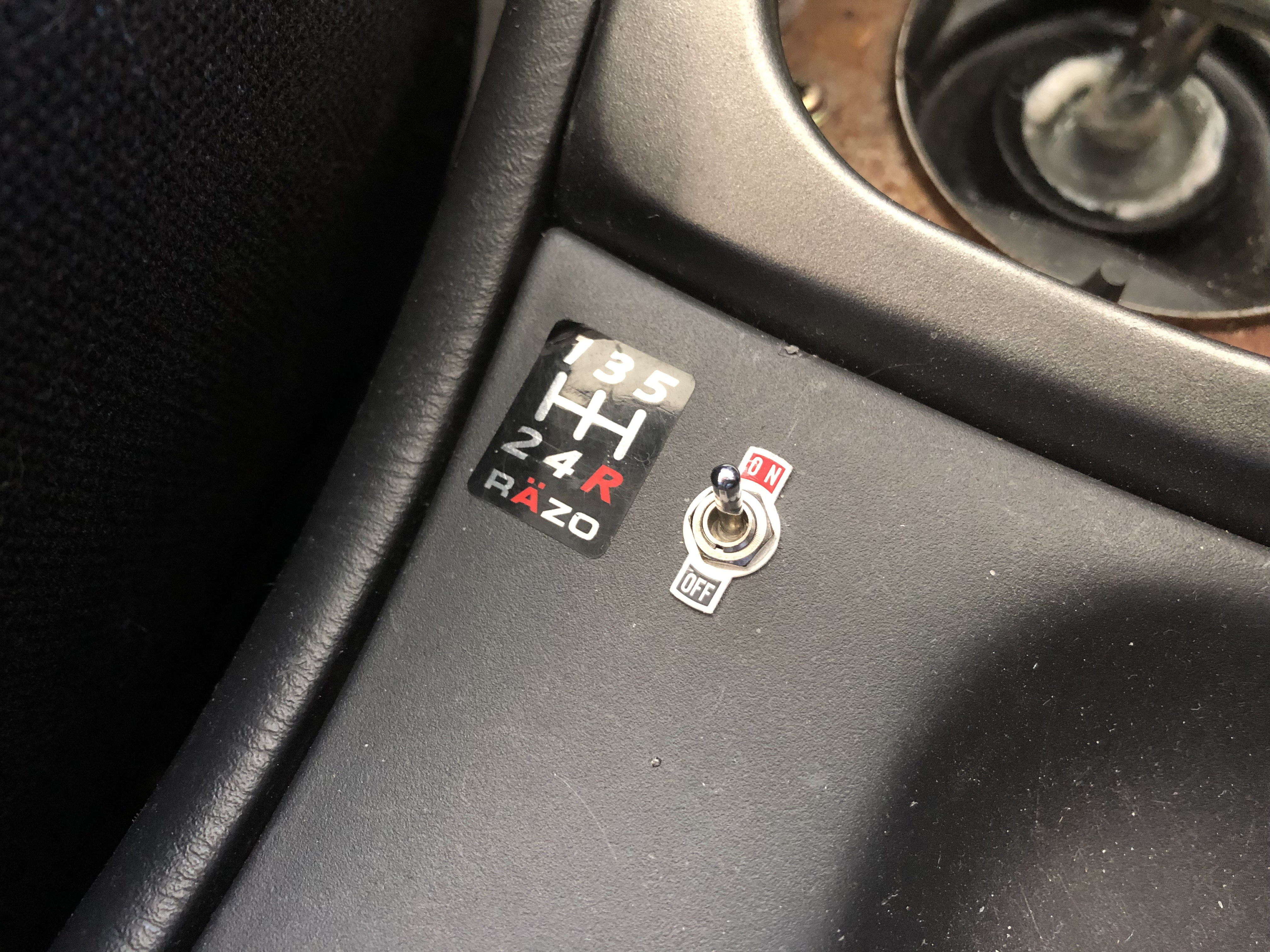
The final version uses a loop instead of a delay, and edges every 290 iterations. This allows me to get a varying value between 176 and 182km/h, while still being able to do some “teensy multithreading” (I hate that). I added a mecanical switch next to the handbrake to engage or disengage the bypass circuit (in case something wrong happen, I can just fallback to the original one).
And finally, the results:
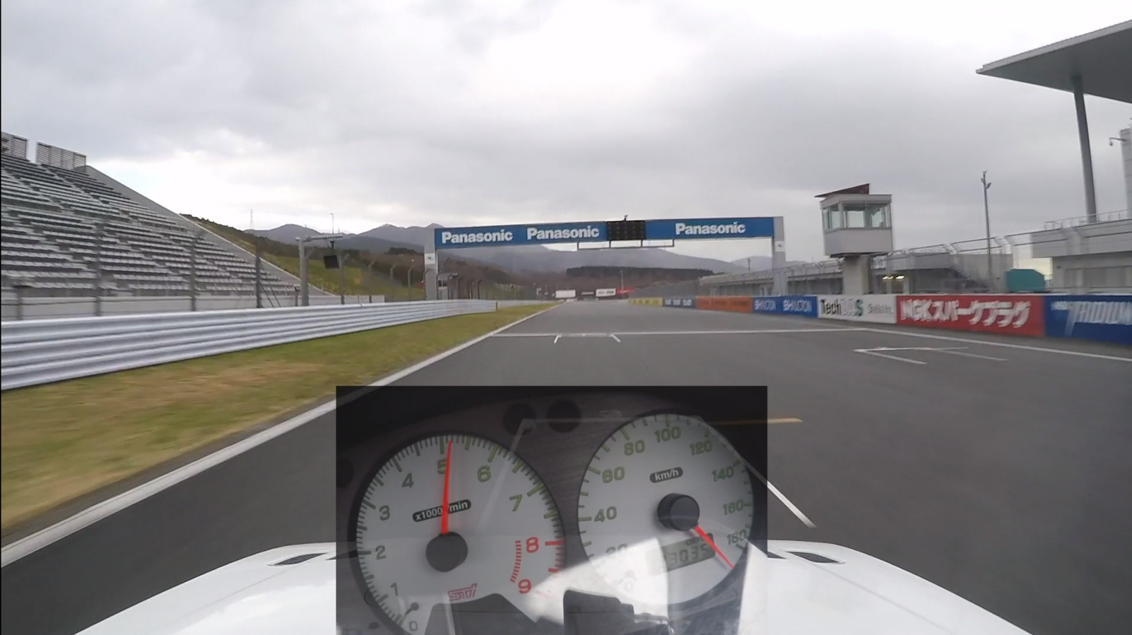
Fuji Speedway’s straight, with speed limiter ON (max speed: ~186km/h)
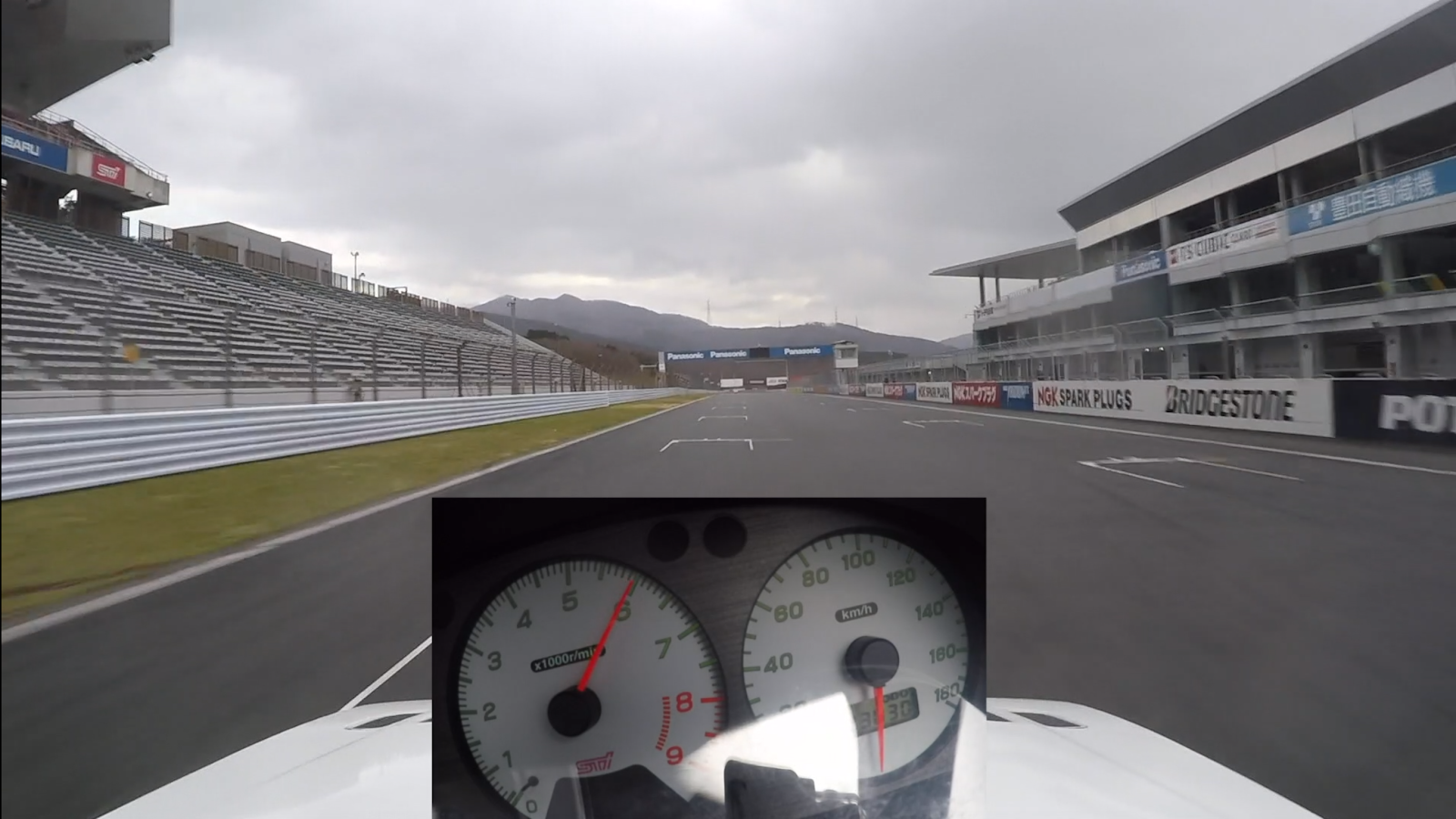
Fuji Speedway’s straight, with speed limiter bypass (max speed: ~220km/h, but it rained so I needed to brake early to be sure I could stop :))) )
Video demonstration is available on Youtube.
Most of this is now available on Github, meaning the code that I use to query information for the IVI, the code used to dump the firwmare, and the code used to modify the VSS signal. I won’t publish the firmware dump for legal reasons (I’m not 100% sure about Japan’s position, but let’s be safe).
Thanks for reading, questions and comments are welcomed through Twitter. If you find anything invalid or that could be better explained, feel free to correct me :)
Thanks to Phil’s website Alcyone and zours for his help during the hardware phase!
UPDATE (19/03/27): After some further testing, it seems that preventing the speed to reach the ECU will make it go into some kind of limp mode after a short time (maybe 45 seconds/1 minute). I haven’t had time to actually look into it more, and need to test if the same thing happens when I send my dummy ~180km/h signal. So cutting your speed sensor wire to get rid of the speed limiter will surely not work, at least on this car/ECU.
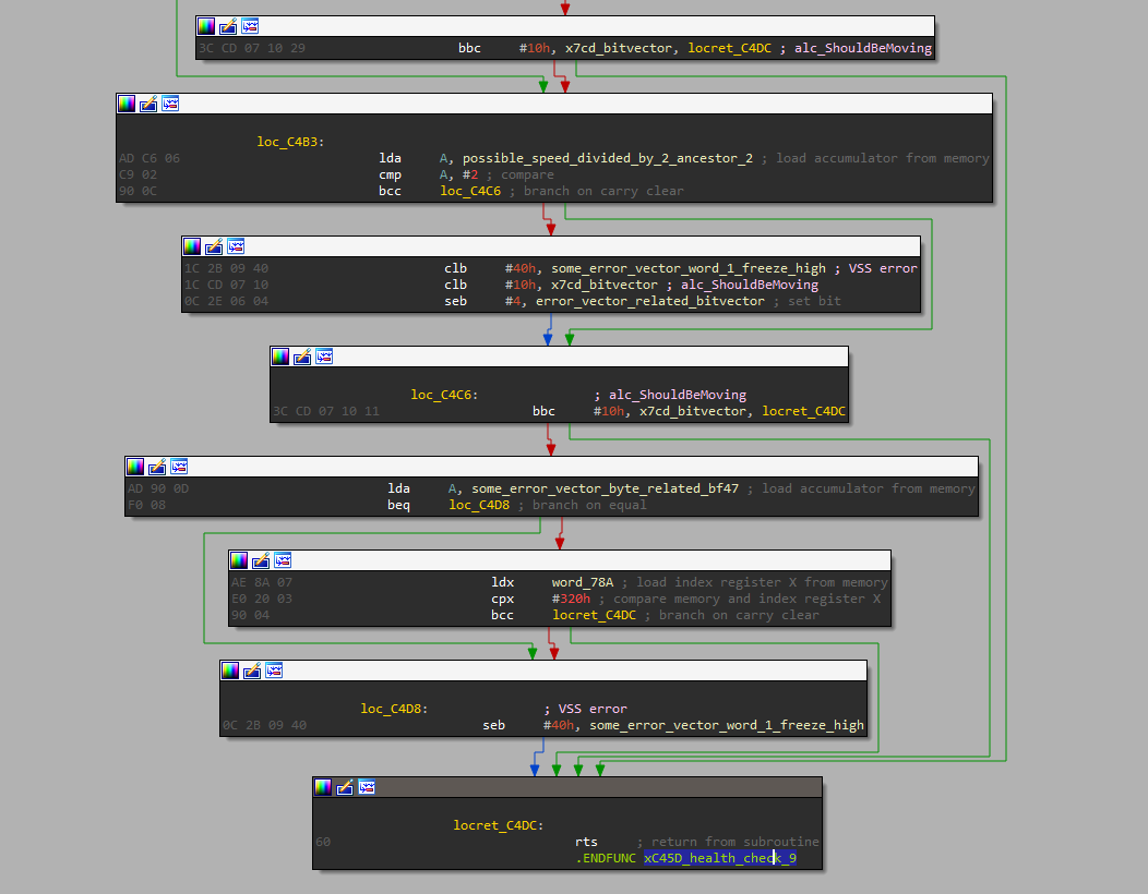
UPDATE (19/06/06): Digging a bit more into the ECU shows that there are
actually multiple checks done while the car is running to ensure that all the
sensors are working correctly. Among those tests, I found that a combination of
checks on the transmission’s neutral switch, engine RPM, throttle pressed
and/or VSS could trigger a VSS error code that later forces the ECU to enter
said strange limp mode, cutting power. Those checks are done quite often as
reactivating the original speed signal brings power back immediately (or at
least, it feels immediate). Following is part of the tests triggering the VSS
error (xC45D_health_check_9 is the function responsible for the VSS).
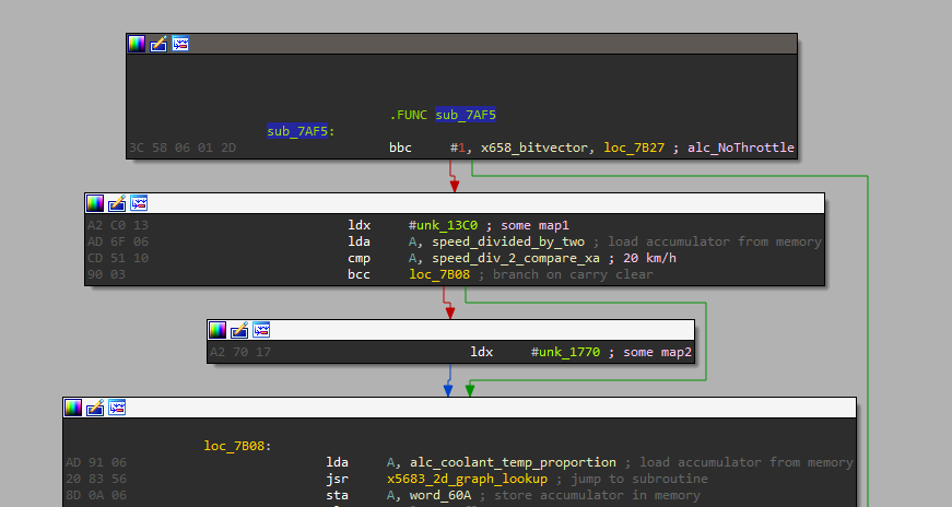
UPDATE (19/06/11): Follow up on the Interlude: Maps and speed sensor. After some further looking into the ECU’s firmware, I was able to find at least one code example that uses the speed value to choose between two different 2D maps. This confirms that completely removing the speed signal from the ECU (by cutting the wire for example) can have unintended effects on engine management.
Sources
- Mechanics SE - How is engine load determined
- Alcyone (most useful resource for this project)
- THAT MANUFACTURER’s engine in a VW van
- SVX ECU reverse
- R32 speed limiter
- VSS info
- Arduino and SSM1 (RU)
- A few more in the repo…